| Markenbezeichnung: | Sinuo |
| Modellnummer: | Die in Anhang I der Verordnung (EU) Nr. 182/2011 aufgeführten Daten sind zu berücksichtigen. |
| MOQ: | 1 |
| Preis: | Customized |
| Zahlungsbedingungen: | T/T |
| Versorgungsfähigkeit: | 5 Sätze pro Monat |
Automotive Rain Test System Automotive Rain Simulation Test System
Complied Standards & Clauses
Conforms to IEC 60529 Degrees of protection provided by enclosures (IP Code);
Product Overview
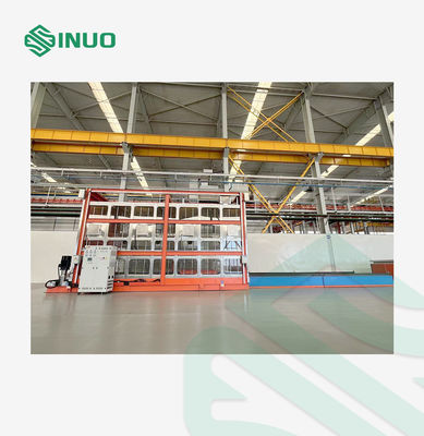
1. The automotive rain test chamber primarily consists of the chamber structure, spray system and control mechanism, air blowing device, control console, foundation (including filtration tank, clear water tank, grit chamber, and water passage), water treatment system, and safety devices.
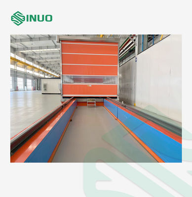
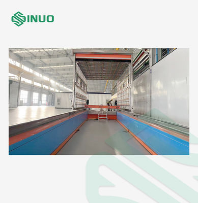
2. The rain test chamber is a one-piece structure with front and rear doors. Vehicles enter from the front, pass through the spray section for the spray test, then proceed to the drain and dry section where surface water is blown away with a high-pressure air gun before exiting through the rear door. The spray section is 7 meters long, and the drain and dry section is 5 meters long.
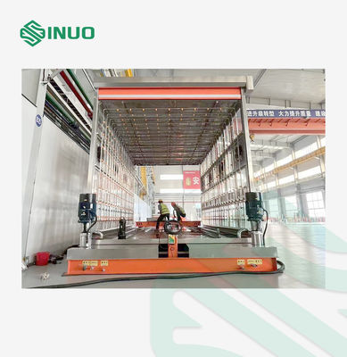
3. The spray system primarily consists of a negative pressure water storage tank, water pump, gate valve, solenoid valve, main line, branch line, and adjustable PP nozzles. The top and front and rear spray pipes are adjustable in distance to accommodate different vehicle dimensions.
4. The pipes are distributed on the support structure, which includes side supports, bottom supports, top supports, front movable supports, and rear movable supports. (The rainproof sealing test device must ensure that water sprays the work piece from all directions, avoiding blind spots and areas without rainfall, and ensuring that the water spray pressure meets the required requirements.) Pressure gauges and flow meters are installed on each branch pipe and main pipe. The rain intensity meets the requirements of the national standard QC/T 476-2007. The flow pipes are made of stainless steel and are equipped with drain plugs at the ends for regular cleaning.
5. The air blowing device uses a high-pressure air source and is arranged with multiple outlets to effectively and quickly blow rainwater off the vehicle body and dry it. The drainage and drying section is equipped with a drain grid on the ground to return dripping water to the circulating water system. The drainage section is 6 meters long.
6. Safety measures are provided, including water level alarms, guide limit alarms, and overpressure alarms.
Technical Parameters
| Power supply | AC380V 50Hz 15kW, and requires an air-powered switch with a leakage protection device |
| Rain time | 0-99h59min59 s presettable |
| Test flow | Calculated according to the standard formula (Q=6FN/625 or Q=3FNS/50), flow control valve adjustment, electronic flow meter collection feedback, computer display |
| Water supply pressure | 69-200±10kPa, adjustable, using pressure sensor to monitor and collect data |
| Spray mechanism pipeline |
Pressure gauges and flow meters must be installed on each branch pipe and main pipe. Rainfall intensity must comply with the national standard QC/T 476-2007. Flow meters must be high-quality, domestically produced. The installation locations of flow meters and pressure gauges must comply with national standards, and the pressure gauge range and accuracy must meet the control plan and process requirements.
Each branch pipe must have a drain outlet at the end and a plug installed to ensure a tight seal. The plug should be made of SUS304 stainless steel.
(Pipeline dimensions are subject to actual production.) |
| Water supply and circulation system |
1) A vacuum tank (SUS304 stainless steel) is installed at the spray pump inlet. A return pipe is installed at the outlet to regulate the spray pump outlet pressure. A bag filter with a filtration accuracy of 200 microns is also installed. 2) Both the spray pump and the sewage pump in the water supply and drainage piping are reputable brands. One spray pump is used, and one is a backup. The sewage pump has a discharge capacity of at least 15 m³/h. 3) Test water is returned from the floor sink in the spray room or the drain section to the sedimentation tank. After secondary filtration, it is transferred to the reservoir, where it is pumped to the spray mechanism. The reservoir is also connected to an external water replenishment system. If the water level falls below the required level, continuous replenishment is required. The sedimentation tank should be cleaned regularly, and the water in the reservoir should be regularly replaced. The water level is automatically controlled by the system based on a water level monitoring device, and an alarm will be issued in the event of water shortage. |
| Interior grille | Strong load-bearing capacity and good drainage performance |
| Control system | The test is controlled by a Mitsubishi PLC, with a computer display and operation. A flow meter displays the water supply pressure, and a pressure sensor monitors the pump's water supply pressure. Control valves control the flow of water in the main, branch, and branch lines, and flow control valves adjust the flow rate in the pipeline to meet standard test requirements. Test item selection, pressure display values, and test time can all be viewed on the computer interface. The interface has both manual and automatic modes. |
| Concrete foundation | The load-bearing foundation, distributed according to the foundation map, including pools, waterways, etc., is built by the customer |
| Leakage recording method | Manual recording, input into computer to print report |
| Vehicle entry and exit methods | Manual entry and exit |
| Laboratory area |
WDH=approx. 14.0m x 6.0m x 3.5m |
Details
![]()
![]()